Charge flows only around a complete loop
Years 5–6 and 9–10Stage 3 and Stage 5Move it
Charge flows only around a complete loop, and all round it at once. Globes transfer its energy as light and heat.
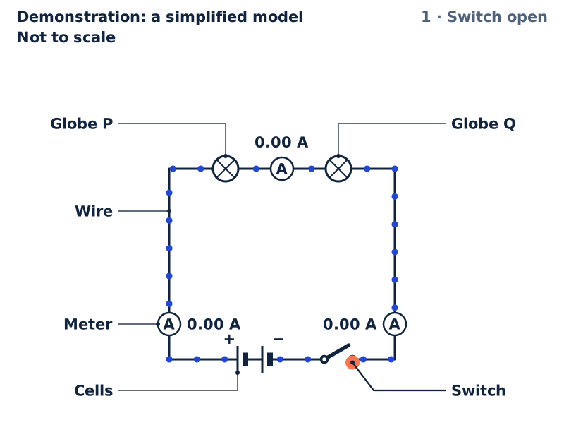
Demonstration: a simplified modelNot to scale1 · Switch open
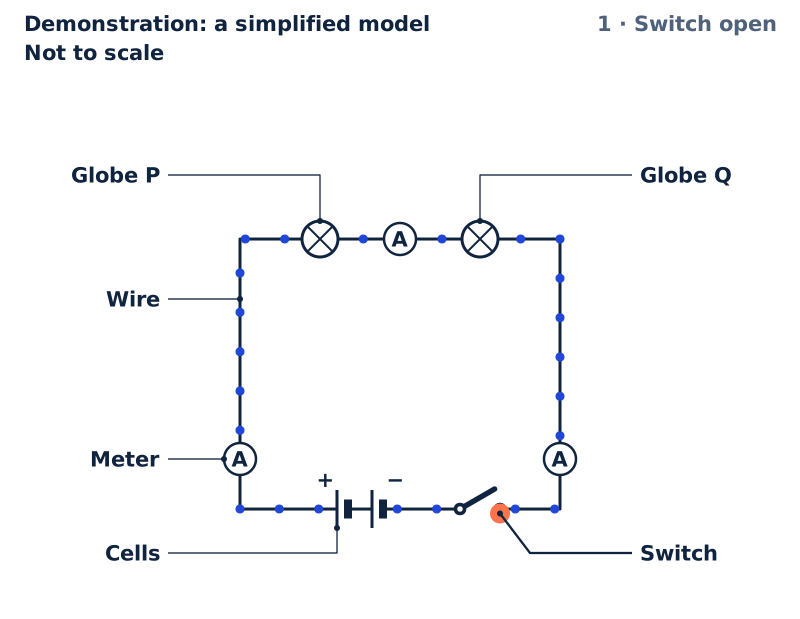
Two globes in series, and the switch is open, so the loop has a gap. No charge flows anywhere: every meter reads zero.
- Globe P
- Globe Q
- Wire
- Meter
- Cells
- Switch
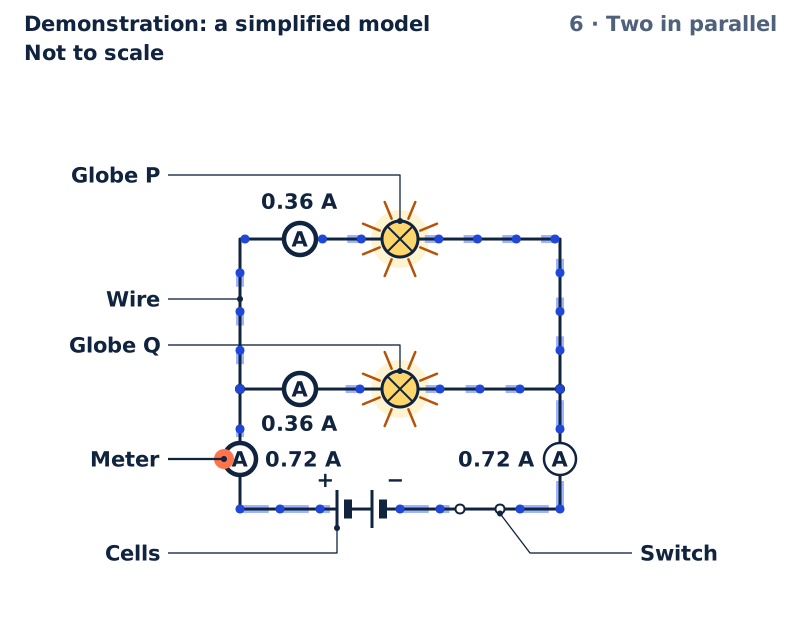
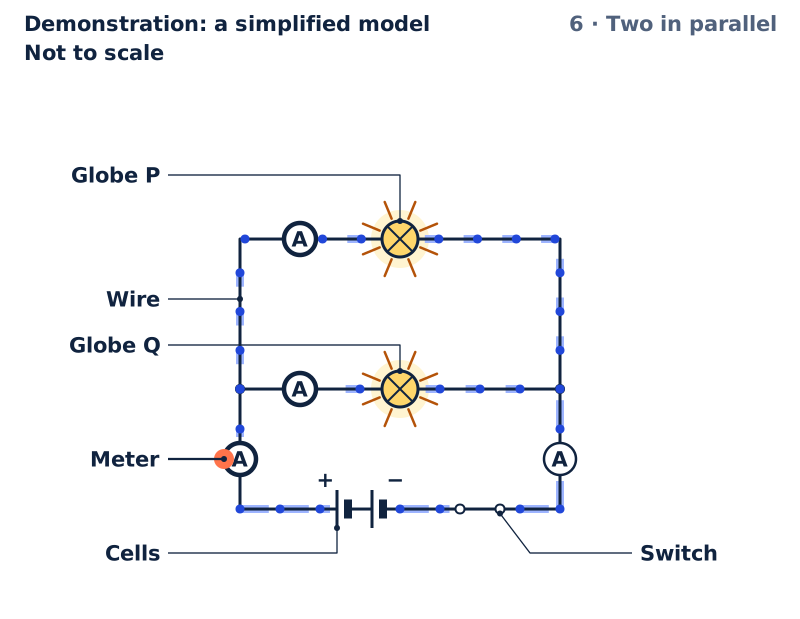
Key Long and short lines: a cell. The long line is its positive (+) side. Circle with a cross: a globe. Rays and a yellow glow: it is lit; the longer the rays, the brighter. Circle with A: a meter that reads the current in the wire, in amperes (A). Switch: closed when its lever touches both rings. Two rings with a gap: globe Q's holder with the globe unscrewed. Filled dot: a junction, where wires meet and the current splits or joins. Blue dots: charge, moving the way the current flows, from the positive side of the cells round to the negative. Pale band behind a dot: the longer the band, the faster the charge moves.
The model could not start here. The figure, the steps and the table on this page still show the idea; reload the page to try again.
The idea, step by step
Not to scale
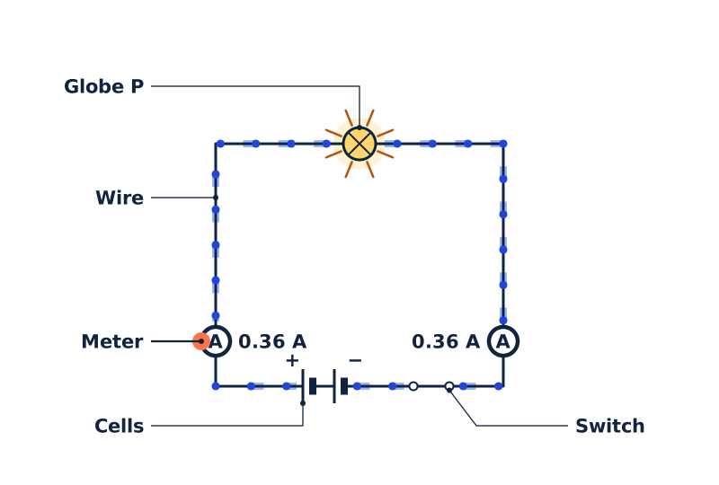
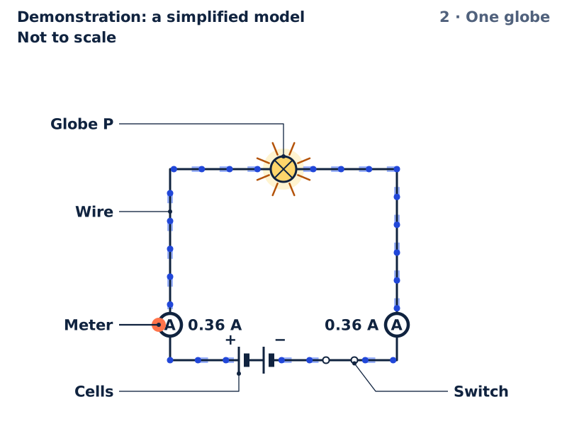
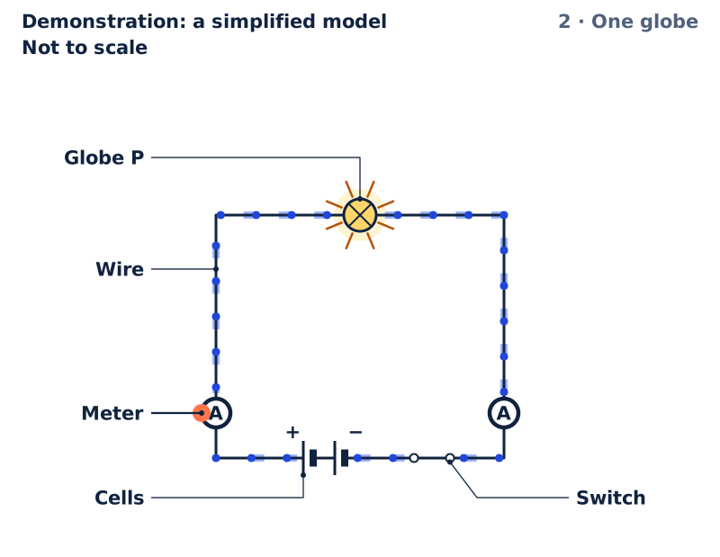
2 · One globeOne globe, switch closed: charge all round the loop moves at once. The meters before and after the globe read the same.1 Globe P · 2 Wire · 3 Meter · 4 Cells · 5 Switch 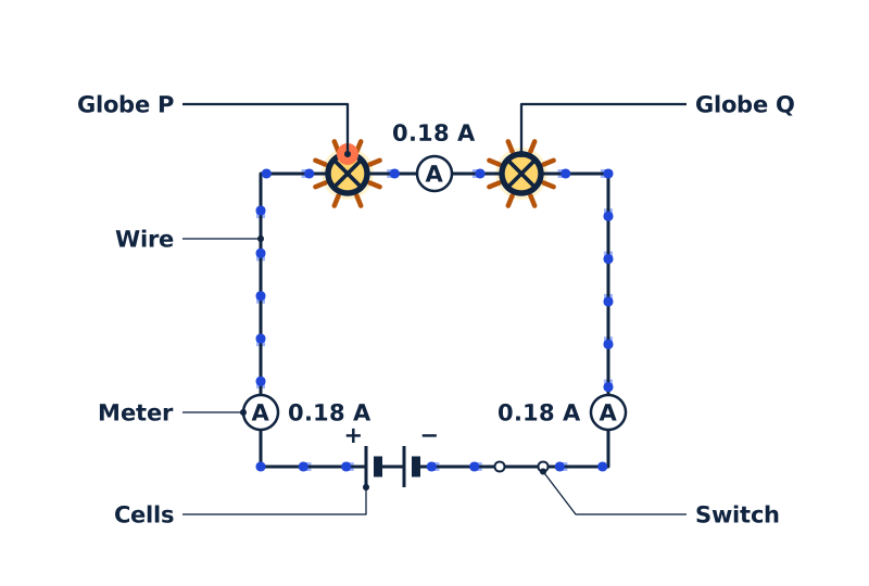
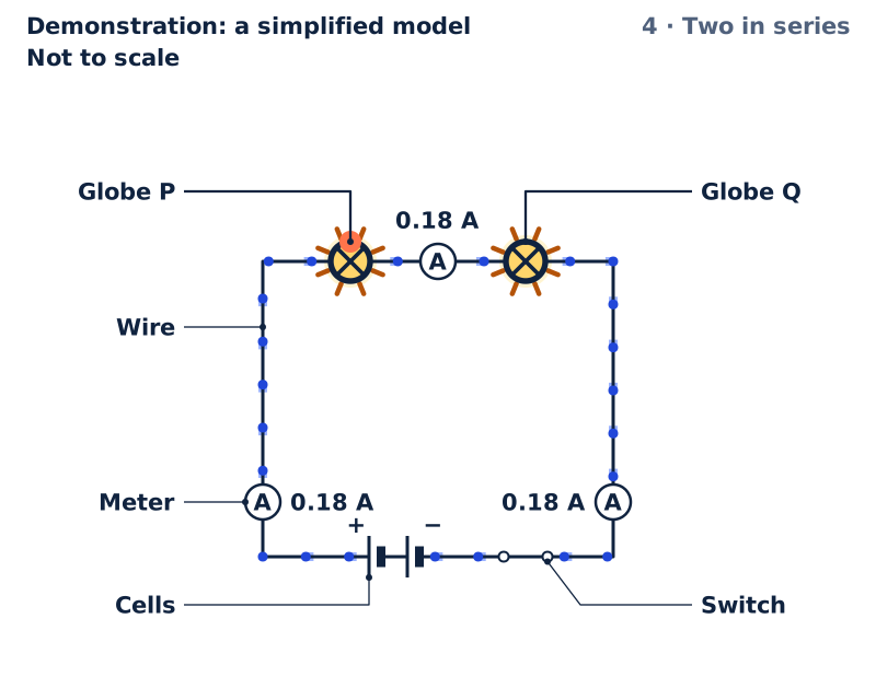
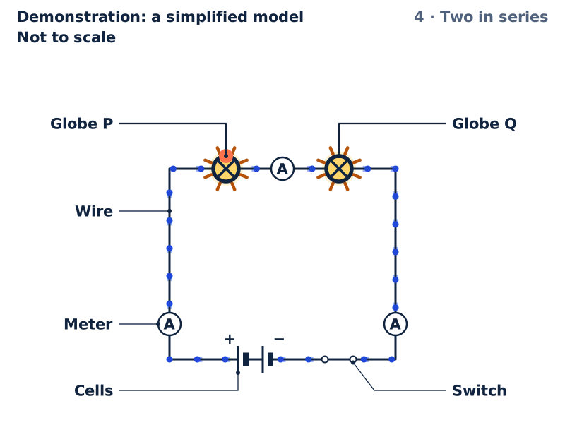
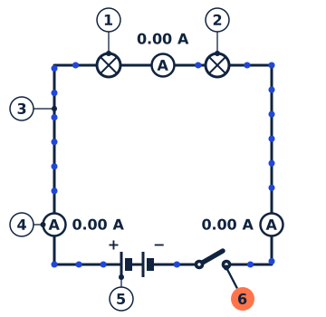
4 · Two in seriesA second globe in series: one path through both. The current is smaller, the same at every meter, and each globe is dimmer.1 Globe P · 2 Globe Q · 3 Wire · 4 Meter · 5 Cells · 6 Switch 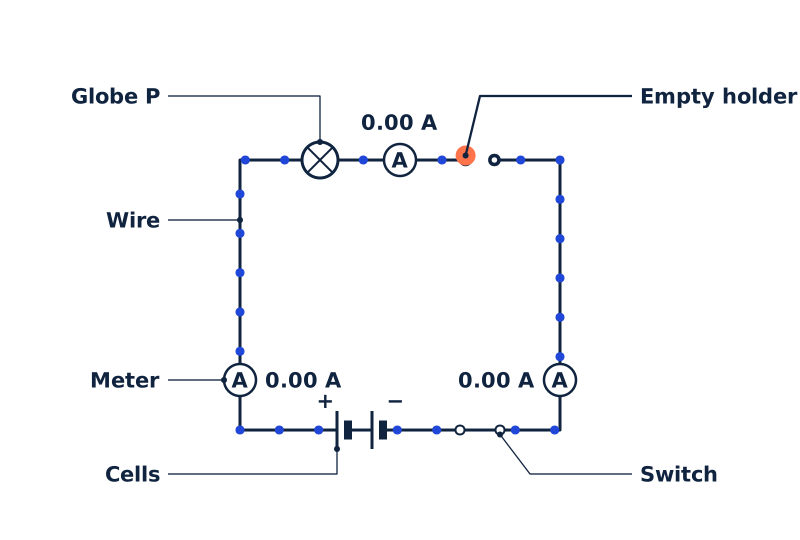
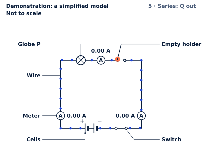
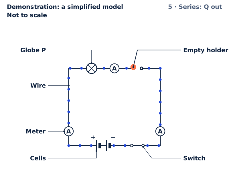
5 · Series: Q outUnscrew globe Q and the only path is broken. No charge flows anywhere, not even up to the gap, so globe P goes out too.1 Globe P · 2 Empty holder · 3 Wire · 4 Meter · 5 Cells · 6 Switch 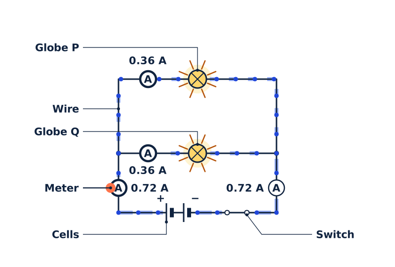
6 · Two in parallelIn parallel each globe has its own branch, as bright as one globe alone. The branch currents add up to the cells' current.1 Globe P · 2 Globe Q · 3 Wire · 4 Meter · 5 Cells · 6 Switch 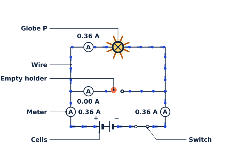
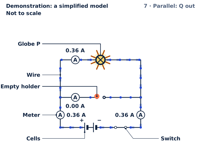
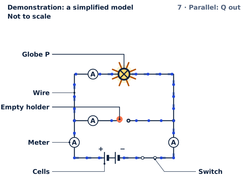
7 · Parallel: Q outUnscrew globe Q: its branch is broken, but globe P's branch is still a complete loop, so globe P stays lit, just as bright.1 Globe P · 2 Empty holder · 3 Wire · 4 Meter · 5 Cells · 6 Switch


One globe, two in series and two in parallel, each with the switch closed, on the cells chosen; a last row for the circuit on the stage when it is none of these
| Circuit | Current from the cells (A) | Current through globe P (A) | Current through globe Q (A) | Globe P | Globe Q | In the first figure |
|---|---|---|---|---|---|---|
| One globe | 0.36 | 0.36 | Bright | No globe Q | ||
| Two in series | 0.18 | 0.18 | 0.18 | Dim | Dim | |
| Two in parallel | 0.72 | 0.36 | 0.36 | Bright | Bright | |
| Switch open | 0.00 | 0.00 | 0.00 | Off | Off | Shown |
Try it in the Lab
Practicals with real materials, each with its safety card.
- Two globes, two ways: series and parallel circuitsYear 6Bench practicalLow risk
- Conductor or insulator? Testing materials in a circuitYear 6Bench practicalLow risk
- Series and parallel circuits: measuring current and voltage with one, two and three lampsYear 9Bench practicalLow risk
- Series and parallel circuits: current and voltage rules from measurementsYear 11Bench practicalLow risk
With a learner
Three questions to ask
- Where must the wires go for the globe to light, and what does the switch do to that path?
- What do the meters before and after the globe show about whether a globe uses up current?
- Why does globe P stay lit when globe Q is unscrewed in parallel, but not in series?
What to expect
Many learners expect the meter after a globe to read less than the meter before it, and the globe nearer the cells to be the brighter one.
What to try next
Open a practical in Try it in the Lab, above, to build the same circuits with real cells, globes and a meter, and compare your readings with the model's.
About this model
What is simplified
- The cells are ideal: they keep their voltage whatever is connected, with no resistance inside. Real cells have a little, so parallel globes glow a little dimmer than one globe alone, and the cells run down faster.
- Each globe is a fixed resistance, the one it has when lit at its rated voltage. A cooler filament has less resistance, so a real dim series pair draws more current than the model shows.
- On two cells a globe gets slightly more than its rated voltage, so it shines brightly and wears out sooner than on its rated voltage.
- Brightness is shown by the power in each globe, in four words: bright, dim, very dim and off. A very dim globe may look off in a bright room.
- The dots stand for charge moving in the direction of the conventional current, from the positive side of the cells round the circuit to the negative. In a metal wire the charges that move are electrons, which drift the other way.
- The dots are drawn far faster than real charge drifts along a wire, which is well under a millimetre each second at these currents. The meters' readings are the model's values.
- The current starts everywhere round the loop at the same moment the switch closes. In a real circuit it settles in far less than a millionth of a second.
- The meters are ideal: an ammeter adds no resistance to the loop, and a voltmeter lets no current through.
- The parts are drawn as standard circuit symbols, not to scale, with the positive side of the cells on the left.
Numbers and their sources
- 1.5 V The voltage of one fresh alkaline AA cell, as its maker's datasheet gives it. The model's cells are ideal: they keep this voltage whatever is connected. Source: Energizer E91 (AA alkaline) product datasheet, form E91NA1018: Nominal Voltage 1.5 volts, read 26 September 2026.
- 2.5 V The rated voltage of the torch globe school circuit kits use, and the Lab practical's. With the rated current it gives the globe's resistance when lit, which the model keeps fixed. Source: Core Electronics, 2.5V MES Globe (CE06963): 2.5 V, 300 mA, read 26 September 2026.
- 0.3 A The same globe's rated current. Source: Core Electronics, 2.5V MES Globe (CE06963): 2.5 V, 300 mA, read 26 September 2026.
Review
Demonstration: a simplified model. Checked against its written sources, 26 September 2026. Not reviewed by a qualified teacher.
Curriculum references
ST3-8PW-STSC5-EGY-01AC9S6U03
Reference, not a verified alignment.